Login for Software/Firmware Downloads

To prevent automated spam submissions leave this field empty.
       

MCCB-500-2

Molded Case Circuit Breaker Tester


9127-UC [110V MCCB-500-2]
9128-UC [220V MCCB-500-2]
9127-SCA [MCCB-500-2 current module shipping case]
9127-SCB [MCCB-500-2 control module shipping case]

The Vanguard MCCB-500-2 is a microprocessor-based high current circuit breaker test set. This unit provides a variable high current source, control, metering, and timing circuitries for testing overload relays and thermal and magnetic circuit breakers. The MCCB-500-2 high output current source can also be used in other primary current injection applications.

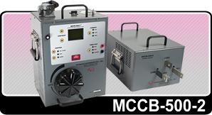
The MCCB-500-2's current source has 3 outputs: 500A @ 4 Vac, 125A @ 14Vac, and 25A @ 70Vac.  The current sources can output short-duration overload conditions. This feature is convenient for performing instantaneous trip tests of molded case circuit breakers, or testing the time delay characteristics of magnetic overload relays.
Test current is measured and displayed on a 128 x 64 pixel back-lit LCD screen that is clearly visible in direct sun light or low light levels. Control switches are used to turn the current source on and off, select the timer stop input type (current mode, dry contact, or wet contact), and control the LCD contrast.
A "momentary" mode can turn on the current source, capturing the current reading and displaying the value on the LCD. This feature can be used to set the test current and minimizes the possibility of overheating the device under test.
Test current is turned on at the zero crossing point using a solid state device for reliability and precision timing.
       

MCCB-500-2

Technical Specifications


PHYSICAL SPECIFICATIONS Control Module
Dimensions: 12"W x 16.25"H x 10"D (30.5 cm x 41.3 cm x 25.4 cm)
Weight: 32 lbs. (14.5 Kg)

Current Supply Module
Dimensions: 12"W x 10"H x 17.25"D (30.5 cm x 25.4 cm x 43.8 cm)
Weight: 67 lbs. (30.4 Kg)
INTERNAL CURRENT METER 1A – 3,000A; accuracy: 1% of reading, ±2 digits 
INPUT VOLTAGE
100 – 120 Vac or 200 – 240 Vac (factory-pre-set), 50/60 Hz
TIMER STOP INPUTS Voltage input (20V – 300V, dc or peak ac), dry contact input, or removal of test current
MEASUREMENT METHOD Isolated CT
DISPLAY
Back-lit LCD screen (128 x 64 pixels); viewable in bright sunlight and low light levels
TIMER READING RANGE 0.1ms – 2 hours (also displayed in cycles); accuracy: 0.1% of reading, ±0.1ms
OUTPUT CURRENTS 500A @ 4V, 125A  @ 14V, 25A @ 70V
INSTANTANEOUS CURRENT 2,500A
HUMIDITY 90% RH @ 40°C (104°F) non-condensing
TEMPERATURE
Operating: -10°C to +50°C (+15°F to +122°F)
Storage: -30°C to +70°C (-22°F to +158°F)
CABLES
  • Two 6-foot (1.8m) #4/0 current cables (Part Number 8000-0183)
  • Two 6-foot (1.8m) #1/0 current cables (Part Number 8000-0190)
  • Two 10-foot (3m) 8 AWG external timer input cables with alligator clips (Part Number 8000-0184)
  • One Control Module to Current Module connection cable (Part Number 8000-0210)
  • One ground cable (Part Number 8000-0110)
  • One power cord (Part Number 8000-0248)
  • Two 10-foot (3m) Timer+Sense Cables (Part Number 8000-0185)
FURNISHED ACCESSORIES Shipping case
SAFETY Designed to meet IEC61010 (1995), UL61010A-1, CSA-C22.2 standards
ALTITUDE
2,000 m (6,562 ft) to full safety specifications
WARRANTY One year on parts and labor